Battery System Integration: Compatibility, Controls, Safety, and Commissioning
Last reviewed July 22, 2026.
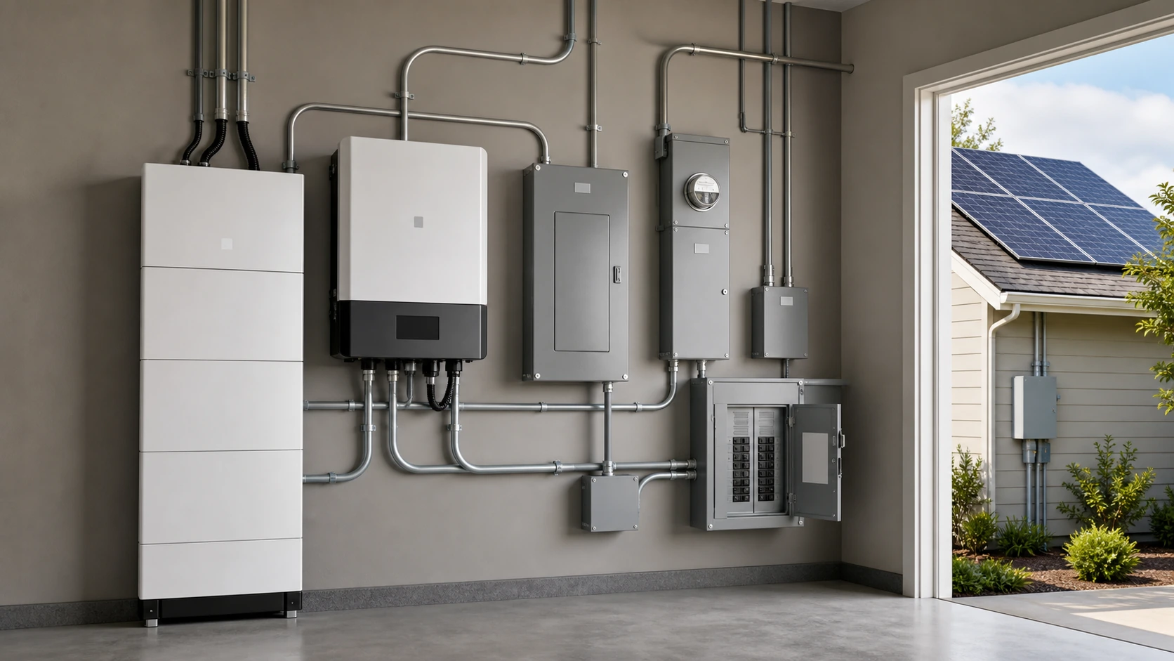
A battery cannot be added successfully by matching capacity alone. Its voltage, charge limits, battery-management system (BMS), inverter or charger, disconnects, overcurrent protection, enclosure, temperature range, transfer equipment, and operating settings must work as one system.
Start with the system boundary
Write down what the battery is expected to do before selecting equipment: reduce evening grid use, carry selected loads through an outage, operate an off-grid site, support a commercial demand target, or participate in a utility program. These goals require different control logic, usable energy, power, transfer behavior, and documentation.
| Question | Why it controls the design | Evidence to obtain |
|---|---|---|
| Which loads must run? | Continuous watts, starting surge, duty cycle, and outage duration determine inverter power and usable battery energy. | Measured load list, circuit schedule, motor or compressor data, and an outage priority list. |
| How will the battery connect? | DC-coupled, AC-coupled, and all-in-one systems use different charging paths, controls, and shutdown behavior. | One-line diagram and exact manufacturer topology instructions. |
| Must it operate during an outage? | A grid-connected inverter does not automatically provide backup. The system needs code-compliant islanding and transfer behavior. | Transfer-equipment manual, backed-up circuit list, and utility/interconnection documentation. |
| Who controls charging? | The BMS, inverter/charger, charge controller, generator, and energy-management system must use compatible limits and priorities. | Communication matrix, supported protocol list, cable part numbers, and current firmware requirements. |
Build a compatibility matrix before buying
Use exact model numbers and manual revisions. “48-volt battery” or “lithium compatible” is not enough information because nominal voltage, allowed charge range, current limits, low-temperature behavior, fault handling, and communication can differ.
- Battery: nominal and operating voltage, recommended and maximum charge current, continuous and surge discharge current, temperature limits, series/parallel rules, BMS protections, and required clearances.
- Inverter/charger: battery-voltage window, charge stages, current limits, low-voltage shutdown, supported BMS protocols, transfer rating, neutral/bonding instructions, surge capability, and supported operating modes.
- PV charge path: array cold open-circuit voltage, hot operating voltage, controller current, battery charge ceiling, rapid-shutdown requirements, and curtailment behavior when the battery is full or unavailable.
- Protection and conductors: listed disconnects, overcurrent devices, conductor ampacity, terminal limits, fault-current rating, grounding/bonding, cable length, and enclosure suitability.
- Controls and monitoring: who sets state-of-charge limits, what happens when communications fail, which faults stop charging or discharging, and whether event logs can behod deliberately
Choose the coupling method deliberately
DC-coupled battery
Solar and battery share a DC-side charging path before AC conversion. This can reduce conversion steps during solar charging, but it makes the charge controller, battery limits, inverter settings, and shutdown sequence tightly dependent on one another. Confirm what happens when the battery is full, cold, offline, or in a BMS fault state.
AC-coupled battery
The battery system connects on the AC side and can be added to some existing PV systems without replacing the original solar inverter. Frequency-shift or other curtailment behavior must be supported by the exact equipment combination.
All-in-one or hybrid equipment
A single enclosure can simplify wiring, but it does not remove compatibility questions. Check the exact supported batteries, communication cable, transfer rating, generator input rules, firmware, parallel-operation limits, and local listing requirements.
Size energy, power, and charging separately
- Build a load list in watts and watt-hours. Separate continuous load, starting surge, and intermittent duty cycle.
- Choose the usable outage or operating window. Reserve settings, temperature, aging, and manufacturer depth-of-discharge limits reduce usable energy.
- Check battery discharge power against inverter demand. A large inverter can exceed the battery's current limit even when the battery has enough stored energy.
- Check every charging source. Solar, grid, and generator charging can overlap; the combined command must remain inside battery and conductor limits.
- Model the recovery case. A backup system that survives one night but cannot recharge under expected weather or generator constraints is not resilient.
Retrofitting an existing solar system
Record the existing inverter model, array configuration, service size, interconnection agreement, production meter, rapid-shutdown equipment, grounding method, and available panel space. Then confirm whether the proposed battery changes the authorized export limit, requires a new interconnection review, changes rapid-shutdown behavior, or needs a backed-up-loads panel.
Do not assume that two products sharing a voltage or brand name are supported for communication. Obtain the current manufacturer compatibility list and verify firmware and cable requirements for the exact combination.
Failure modes to resolve on paper
- BMS communications are lost while charging.
- The battery is below its permitted charging temperature.
- The inverter starts a motor while the battery is near its current limit.
- Grid power returns while the backup system is islanded.
- The generator neutral or bonding arrangement conflicts with the transfer equipment.
- The battery reaches its upper state-of-charge limit while islanded solar is still producing.
- A module in a parallel battery bank disconnects or reports a fault.
- Firmware changes after commissioning.
Commissioning record
Keep the accepted one-line diagram, exact model and serial numbers, manuals and revisions, firmware versions, torque records where required, protection settings, battery charge/discharge limits, BMS communication status, transfer test, shutdown test, backed-up circuit list, owner instructions, and photos of labels and disconnects. The record should state which operating modes were tested and which were not.
Safety and practical limit
Battery integration involves stored energy, high fault current, shock, fire, backfeed, thermal, and equipment-damage hazards. Use listed equipment where required, follow the exact manufacturer instructions, and have electrical, structural, fire-safety, permitting, and utility questions handled by qualified parties for the project location.
Sources
- U.S. Department of Energy: Solar Integration—Solar Energy and Storage Basics — explains the role of storage in solar integration; it does not approve a specific equipment combination.
- U.S. Department of Energy: Homeowner's Guide to Going Solar — planning, installer, permitting, and utility context.
- UL Solutions: Batteries and Energy Storage — listing and safety-services context; the listing status of the exact model still must be confirmed.
- NFPA 855: Standard for the Installation of Stationary Energy Storage Systems — installation-standard scope; locally adopted requirements and editions vary.
How to verify the numbers on this page
This page covers Battery System Integration: Compatibility, Controls, Safety, and Commissioning. Figures here depend on the exact model, site, policy, study, test method, operating conditions, system boundaries, and comparison baseline. Verify current manufacturer, regulator, standard, or primary-research documents before acting.
Additional primary and technical references
Use this technical reference alongside exact battery, BMS, inverter, protection, commissioning, and installation documents for the selected system.