How to Charge a LiFePO4 Battery: Voltage, Current, Temperature, BMS, and Bank Configuration
Last reviewed July 8, 2026. Confirm equipment settings, tariffs, incentives, warranties, safety requirements, utility rules, and local code with current official documents and qualified professionals before acting.
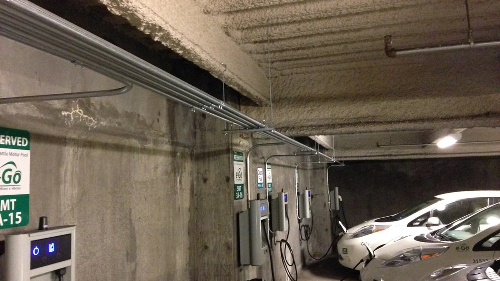
Direct answer: charge a LiFePO₄ battery according to the exact manufacturer instruction sheet for that model — never a generic lithium profile — using a charger or charge controller whose voltage and current settings match the battery's published limits, with charging blocked or derated below the battery's minimum permitted temperature. There is no single voltage that fits every LiFePO₄ pack: cells, packs, drop-in batteries, series banks, and parallel banks each have their own limits and behavior.
Cell, pack, drop-in battery, and bank distinctions
- Individual cells. A LiFePO₄ cell has a nominal voltage near 3.2 V. Its maximum charge voltage is set by the manufacturer (commonly around 3.6–3.65 V) and its minimum discharge voltage by the same datasheet.
- Assembled packs. A pack of series cells (for example, 4S at roughly 12.8 V nominal, 8S at 25.6 V, 16S at 51.2 V) has a pack-level charge voltage limit that is the cell limit times the series count, and it depends on the BMS balancing design.
- Drop-in batteries. "Drop-in" replacement batteries for lead-acid footprints usually contain their own BMS and may accept a lead-acid charging profile within a stated voltage window, or may require a lithium profile. The exact manual decides; the label alone does not.
- Series banks. Adding cells or packs in series raises the bank voltage. Every series unit must be matched in capacity, chemistry, and state of charge, and the bank's charge voltage is the sum of the units' limits.
- Parallel banks. Parallel units keep the same voltage and add capacity and current capability. Units must be matched in voltage and state of charge before connecting, and each unit's BMS must permit parallel operation at the expected current sharing.
- Stationary and portable systems. Stationary solar storage usually charges from a solar charge controller or inverter-charger with defined set points; portable systems may use bench chargers or vehicle alternators, each with its own limits and risks.
Charging stages and what each does
- Bulk (constant current). The charger delivers its set current while voltage rises to the target. The current limit is the lower of the charger's rating, the battery's published maximum charge current, and the BMS limit.
- Absorption (constant voltage). Voltage holds at the target while current tapers. LiFePO₄ reaches full charge when current falls to the manufacturer's termination threshold at the target voltage.
- Float. Some LiFePO₄ batteries permit a float voltage below the full-charge voltage for storage or load support; others specify no float at all. Float is not automatically required or harmful — the manual governs.
- Equalization. Equalization is a lead-acid procedure. Do not apply equalization to LiFePO₄; the voltages can exceed cell limits and trigger BMS protection or damage cells.
Voltage and current limits: illustrative table
| Parameter | Typical published range | Status |
|---|---|---|
| Cell charge voltage limit | ≈3.6–3.65 V per cell | Illustrative — the exact datasheet governs |
| Pack charge voltage (4S) | ≈14.4–14.6 V | Illustrative — varies by pack and BMS |
| Recommended charge current | Often 0.2C–0.5C; some cells allow 1C | Illustrative — the datasheet governs |
| Minimum charge temperature | Often 0°C; some cells −10°C or lower with reduced current | Illustrative — model-specific, never assumed |
| Float voltage (where supported) | Below full-charge voltage, e.g. ≈13.6 V for 4S | Illustrative — only where the manual specifies float |
The values above are typical published ranges for orientation. Charging any battery at values taken from a table like this, instead of its own datasheet, is exactly the error this page warns against.
Low-temperature charging warning
Charging LiFePO₄ below the manufacturer's minimum temperature can cause lithium plating that permanently reduces capacity and can create safety risks. Do not bypass a low-temperature block "just this once." Where the battery supports it, the BMS or charger inhibits charging below the threshold, or reduces current in stages; the exact thresholds and hysteresis are in the battery manual. A heated battery enclosure or a charger with a temperature sensor can permit charging in cold installations only if the equipment is designed for it.
BMS cutoff is not a charging strategy
A BMS that disconnects at its protection limits is a last-resort safeguard, not a normal control method. Regularly driving the battery into BMS cutoff (for example, setting a charger voltage above the pack limit and letting the BMS interrupt the charge) stresses the pack, can cause nuisance disconnects, and can leave loads unpowered without warning. Configure the charger to stay inside the battery's normal operating envelope so protection trips remain abnormal-event safeguards.
Charger types and their limits
- Solar charge controllers. Use a lithium battery profile if the controller supports it, or set the controller's custom voltage and current limits to the battery's published values. Confirm the controller's temperature compensation is disabled or set for lithium where the battery does not require lead-acid compensation.
- Inverter-chargers. Set the charge voltage, absorption time, and charge current to the battery manual's values, and confirm the inverter's BMS communication (CAN, RS485, or vendor protocol) matches the battery's protocol if closed-loop control is used.
- Bench chargers. Only a charger with a LiFePO₄ setting (or fully adjustable set points) is acceptable. "Any lithium charger" is not: lithium-polymer and lithium-ion chargers may use different voltage targets than LiFePO₄.
- Alternator charging. Vehicle alternators are not battery chargers; they need an appropriate DC-DC charger between the alternator and the LiFePO₄ battery to limit voltage and current, and to handle the battery's low-temperature rules.
Series and parallel banks: matching and balancing
Before connecting units in series or parallel, match voltage and state of charge, and use the manufacturer's connection order. Balancing is not automatic: passive balancing in a BMS typically acts only near the top of charge, and active balancing moves energy between cells but cannot repair mismatched capacity, age, or chemistry. Top balancing (bringing series cells to a common full state under controlled conditions) is a build or service procedure, not a routine of normal operation. A bank assembled from mismatched units will limit the whole bank to its weakest unit and can trigger repeated protection events.
Storage charging
For storage, charge to the manufacturer's recommended storage state of charge — often 50–80% rather than 100% for long periods — and follow the stated temperature range and recharge interval. A battery stored at full charge at high temperature ages faster than one stored at a moderate state of charge and temperature.
Troubleshooting: symptoms of incorrect settings
| Symptom | Likely cause | Check |
|---|---|---|
| Charger shows full, battery shows low under load | Voltage-only full detection on a flat LFP curve, or wrong absorption voltage | Verify the charge termination rule and voltage target against the manual |
| BMS disconnects during charge | Charge voltage above the pack limit, or charge current above the BMS limit | Set charger limits inside the battery envelope |
| Charging stops in cold weather | Low-temperature protection active | Confirm the threshold and whether a heated enclosure is required |
| Battery never reaches full | Absorption time too short, termination current wrong, or parallel units mismatched | Compare settings with the manual and re-check bank matching |
| Capacity drops after a few cycles | Deep discharge below the cell minimum, high-temperature operation, or low-temperature charging | Review the operating history against the datasheet limits |
Exact-manual checklist
- Battery model and revision; the exact charge voltage and current limits from its datasheet.
- Minimum and maximum charge temperature and any derating curve.
- Whether float is specified, and at what voltage.
- Termination current or absorption-time rule for "full."
- BMS communication protocol and compatibility list for closed-loop charging.
- Series/parallel connection rules, including state-of-charge matching and connection order.
- Storage state of charge and recharge interval.
Sources
- The exact battery manufacturer's instruction sheet and datasheet are controlling for every value on this page; the tables here are illustrative orientation, not a substitute.
- Battery University BU-409: Charging Lithium-ion: charge-stage behavior and termination for lithium chemistries.
- Battery University BU-903: How to Measure State-of-charge: why the flat LiFePO₄ voltage profile makes voltage-only charge detection unreliable.
Government and code references
Use these sources as starting points when the page affects a purchase, design, tax, utility, safety, or policy decision.